

Tips & Tricks
How can I create a multi-colored glow effect? SW
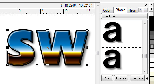
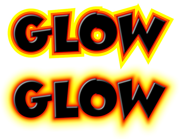 To create a single colored glow, you would use the Glow feature. But to create a multiple colored glow, you need to use a combination of Outline and Feather. Start with your original object and add two or three Outlines, each a different color. In the Layers Tab, select the first Outline and then apply Feather from the Effects Menu and set the value to your liking. Do the same with the second and third outlines and the colors will blend together.
In this example, we used an 8% Feather on the first two outlines, and then 24% on the third outline, which is also considerably thicker to give a nice glow effect.
How do I turn off the Tube Numbers for plotting? NW
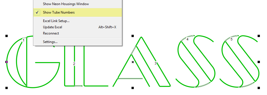 The Tube Number displays on each tube are useful when you are designing and also for matching up the tubes to the footage stats, but you probably don't want to plot them. You can turn them off in the Neon Menu, Show Tube Numbers before you Plot.
Shortcuts using the Layers Tab SW NW LW
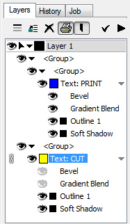
The Layers Tab has many functions and shortcuts that you should be aware of.
- Toggle the view of an entire object or group on and off, as well as a particular element only, such as an outline or shadow.
- Select an element of a Group that may be difficult to select otherwise, such as the second or third outline, or a Power Supply in LED Wizard.
- Select and edit an Effect by double clicking on it in the Layers tab (this is the equivalent of selecting an object and going to the Effects Menu and selecting the effect you want to edit).
- Change the Z order of groups, objects, and layers by dragging them up and down in the Layers tab.
Managing your Image Fills Library SW
The Image Fills feature enables you to put a scalable, seamlessly tiled image inside your text or graphics. It is the perfect merge of raster and vector graphics, since the shape is defined by vectors and the image can be tiled to large sizes without loss of quality. These images are saved into various folders in your Image Fills Library, and there is a dialog box to manage the files.
You have the option of adding new image tiles to the library, as well as editing the existing files in the library. To add a new file, you can either drag the files into the Image Fills Library dialog box and Import them, or simply open the file in Sign Wizard and use the Add to Image Fill Libraryfunction in the Image Menu.
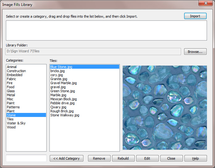 To edit one of the files from the library, you can open it from the Image Fills Library dialog box using the Edit button. Then make whatever adjustments you want, such as contrast, hue, or saturation, and save the file back to the library with a new name using the Add to Image Fill Library option in the Image Menu.
In this dialog box, you can also Add a new Category, which would then be included in the drop down list when you are browsing the image tiles.
If you are adding new images to the library, be careful to use files that are either very uniform, such as a texture, or that have a repeating pattern.
If you want to put a regular image inside text, such as a sunset or cityscape, then use the Clipping Path or Photomask features instead (these are not designed to tile the image).
Creating an Export Profile LW
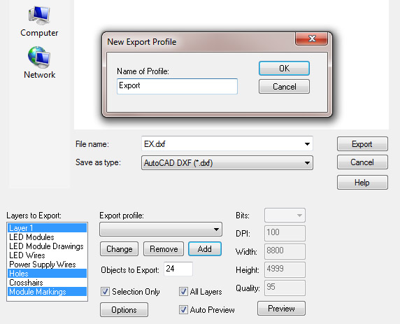
One of the important capabilities of LED Wizard is to export a full scale production file that contains only certain layers, such as:
- Layer 1 (the letter outlines)
- Mounting holes
- Module holes
- Router Layer (module markings)
When you select Export, the default is to include All Layers, so you have to uncheck each layer in the Layers to Export box until you get to just the layers you want. But instead of doing this each time, just set up an Export Profile! Click on the Add button below the Export profile drop down list and give your profile a name. In this example, I selected Layer 1, Holes, and Module Markings. Now the next time I export, I just select this new Export Profile for these three layers. You can add multiple Export Profiles.
Import Crop SW NW LW
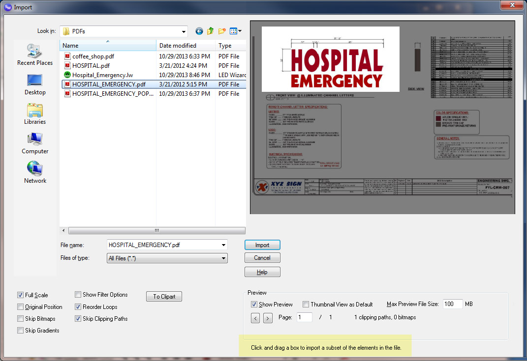 The Import Crop feature lets you crop a file right in the Import dialog box before bringing it into the layout. This can be very useful when you have a large design file, but you just want to import a subset of the file.
Here in the Import dialog box, just draw a box with the left mouse button around what you want to keep from the file and then click on Import. Please note that this is not a bitmap crop; you need to have vector data in the file to crop.
Speed up your designs using Text Styles SW NW
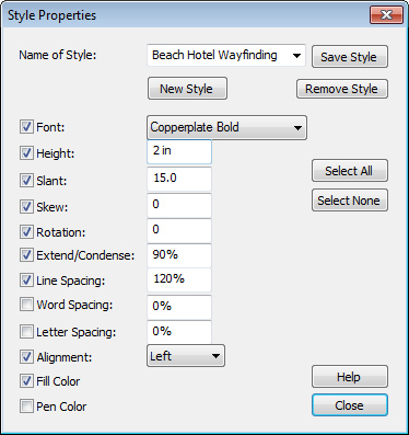 Similar in concept to the Effects Library, the Text Styles capability lets you create, save, and reuse your favorite text attributes. In fact, when used together, the Text Styles and Effects Library can enable you to create terrific looking text in no time.
A particular style can have many attributes, or only a few, depending on which ones you check. In this example, this Text Style was for wayfinding signage at the Beach Hotel. The lettering is 2” Copperplate Bold with a 15 degree Slant and Condensed to 90%, among other attributes. Every time you have work on this job, just select the Text Style and start typing.
Making a Title Block Template LW
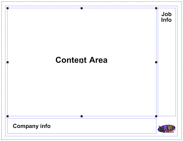 Setting up your own title block template is easy and it's a great way to customize and brand your layouts. A title block template is simply an LED Wizard file that contains a "Content" area where your layout goes, and then standard company and job information around the outside. It is best to design your template to match your print size and orientation. So for example, if you print your layouts on an 8.5x11" or A4 landscape page, then design your title block file at this size. You can include both vector and raster graphics in your title block file, but be careful of making it too large because it will make all of your files that much bigger!
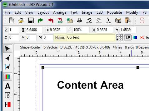 Lets look at a very simple example to go over the process. Here is a layout that is 8.5x11", with a bottom rectangle for company info, a right side rectangle for job info, and a content rectangle in the middle where the actual layout will go. You have to name that rectangle "Content" as shown in the right image. This tells the software that you want your job to be placed inside that rectangle when you click Merge. (Please note that the title block file is proportionately scaled UP to match the LED layout; LED Wizard always operates at full scale.)
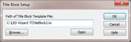 Now just save that file as a normal .LW file. Go to the Options Menu and then select Title Block Setup. Enter or browse to the path of the file you just saved so the software knows where to find your title block file. Click on OK and then you're all set. Now when your job is finished, just click on the Merge icon or use the shortcut key F7! Please note that you can have multiple Title Block Template files, perhaps a vertical version, or even customized to a particular product.
How do I export a transparent bitmap? SW
![]() The best option here is to export using the PNG format with 32 bits. This will preserve transparency and allow you to place the exported file on top of another background without having a white bounding box.
The best option here is to export using the PNG format with 32 bits. This will preserve transparency and allow you to place the exported file on top of another background without having a white bounding box.
Also note in this screen shot that there is a Transparent Background (checker pattern). You can select this kind of background in the View Menu, Transparent Background.
Transparency is also supported with 32 bit PNGs where the image itself blends into the background.
![]()
![]()
Vector Editing Tips for Deleting Points SW NW LW
There are lots of different capabilities in the Vector Edit Tool, but certainly one of the most common tasks is deleting nodes. Maybe the artwork isn't smooth or you just want to make sure that a line is really straight. Aside from the Optimize Vectors function, which is a "global" function that works on the entire object, there are two quick and easy tools for deleting nodes:
Draw a box around the nodes you want to delete. This is pretty simple. It will work on multiple loops of the same object, but not on a different object in a Group. If you want to delete points across multiple loops, then Combine the objects first. You cannot delete the Start/End point this way (and therefore an entire loop), but otherwise there are no restrictions and its a quick way to delete a lot of points. (Please note: if you hold SHIFT while drawing the box, then it will Select multiple points, not delete them!)
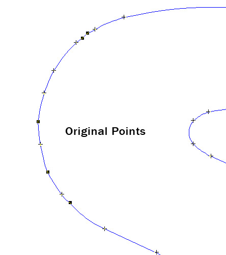
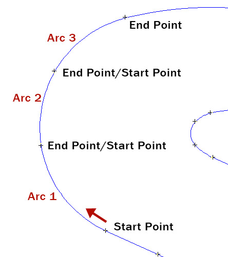
Use the ALT-Smoothing technique. This is one of my favorite features for its simplicity and productivity. The basic concept is that you are selecting two end points in a series of nodes and deleting all vectors in between, leaving just one arc that approximates the previous path. Start with one end point by clicking on it. Hold the ALT key and now click on the other end point in what will become your new arc. All the points in between will be deleted. If you continue to hold down the ALT key, you can now continue to the next set of points. This is the best way to smooth out rough patches, but remember that the result is an arc, not a Bezier curve, so choose your start and end points so that the arc is faithful to the original path.
Using Auto Weld with Dynamic Effects SW
The concept of Dynamic Effects is simple: you can always go back and change the properties of the effect down the road. This includes the cases where you have multiple effects on the same object. But what makes this really terrific is the added ability to also change the text, change the font, change the kerning, change the scale, and more.
You have probably seen this ability in our videos and hopefully use this in your everyday work on Sign Wizard Pro 7. One additional capability that I want to highlight here is the use of the Auto Weld option in Paragraph Text. It used to be that Welding text turned it into a Graphic, but now you can Weld "on the fly" and then Unweld by changing the kerning or changing the font.
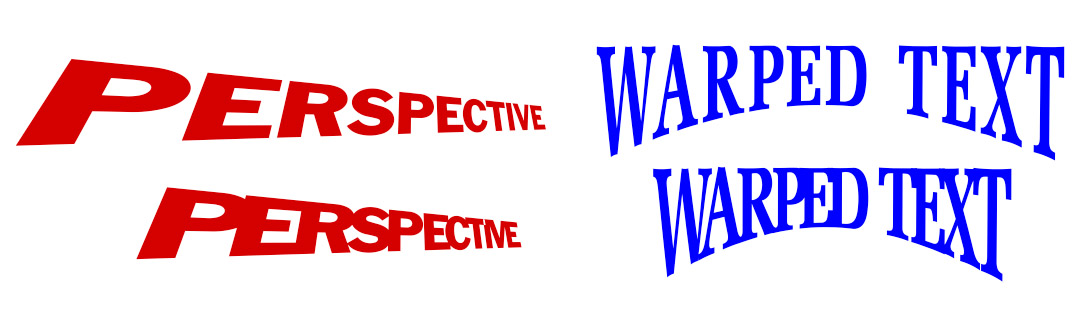 Some of our old favorite distortions are now dynamic and can be used with Auto Weld, includingWarp, Sphere, Cylinder, and Perspective. The Map to Path and Map to Circle options in Paragraph Text can also use Auto Weld, which is particularly helpful since these features tend to adjust the kerning.
In these examples, Perspective and Warp were applied to this text, then the kerning was adjusted with Auto Weld. In fact, the individual letter kerning can also be adjusted, as it was here between the P and E. Use Paragraph Text and Dynamic Effects for maximum design flexibility, and then save your favorite combinations in the Effects Library!
An alternate way to use your Effects Library SW
If you don't know about the Effects Library, please take five minutes and watch this video! This is one of the most powerful features of Sign Wizard 7 because it allows you to create and reuse design ideas that combine several effects together.
Watch the Video: Effects Library
What I want to talk about here, however, is a different way to use the Effects Library from what is shown in the video. This approach focuses more on building a composite of effects one at a time. The Effects Library is divided into the following categories: Complete Effects, Gradients, (Image) Fills, Bevels, Feather, Outlines, and Shadows. Instead of (or in addition to) creating "Complete Effects" with multiple effects together, you can create a series of individual effects, such as various outline thicknesses or shadow styles, and apply them sequentially to "build" the final composite effect.
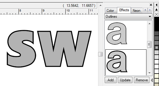
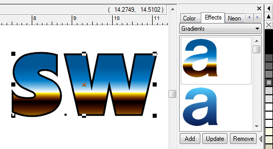
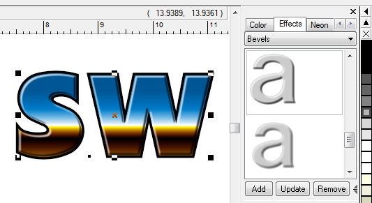
Using the Effects Library in this way is almost like a shortcut with these various effects - in this case you have pre-created the Outlines, Blends, Bevels, and Shadows that you like, and you are just putting them together in different ways.
What is the difference between Break into Loops and Break into Outer Loops? SW NW LW
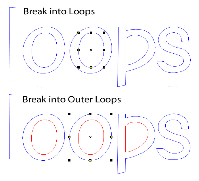 This is an important distinction. Break into Outer Loops will keep any internals with its outer loop. So for example, if you import a set of letters that are Combined into one object, and you want to break them into letters, use Break into Outer Loops and the internals of letters such as A, B, D, etc will be included. Otherwise the internals will be separate, and not the right loop direction. Remember that outside loops are blue and inside loops are red.
How do I draw Dimensions on my designs? SW NW LW
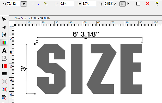 The Dimensioning Tool is very easy to use and gives you several options to customize the dimensions to your liking. Select Dimensions from the Tools Menu or click on the icon in the toolbox, and you'll see that the cursor changes to have a little ruler attached to it. Now just click where you want one end of the dimension to be, and drag the mouse to the other end and release the mouse button. It is easy to adjust the position of each end point, and you can also make other changes, such as where the measurement is shown, the size of the measurement, the style of the arrow, and other details.
What is Outside Angle Threshhold (OAT) and what does it do? SW NW LW
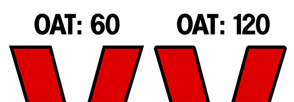 This is an angle that determines at what point an outline/inline or offset will switch from a sharp corner to a rounded corner. It is implemented in slightly different ways across SW, NW, and LW, but the concept is the same.
A value of 0 will not create any rounded corners, and a low number will only round the corners on very small angles. A value of 91 will round right angles, and higher values will round most angles.
How do I take a screen shot? SW NW LW
A screen shot allows you to copy/paste/print any dialog box in any Windows program. With the dialog box you want active, simultaneously press the ALT and Print Screen buttons on your keyboard. This will send the image of the dialog box to the Windows Clipboard. Then in your word processor, email program, image editing program, etc., you can Paste the dialog box using CTRL+V. (If you use just the Print Screen button, it will capture your entire screen.)
Taking a screen shot in this manner can be used for many purposes, including sending Aries Graphics information about a problem you may be having. It is also a very good idea to take a screen shot of your plotter/cutter driver in case you have to reinstall the software.
Using Dynamic Contour Cut SW
Creating a simple Contour Cut path is easy and usually all you need, but consider the Dynamic Contour Cut Path option because it will automatically update if you make changes to the underlying design.
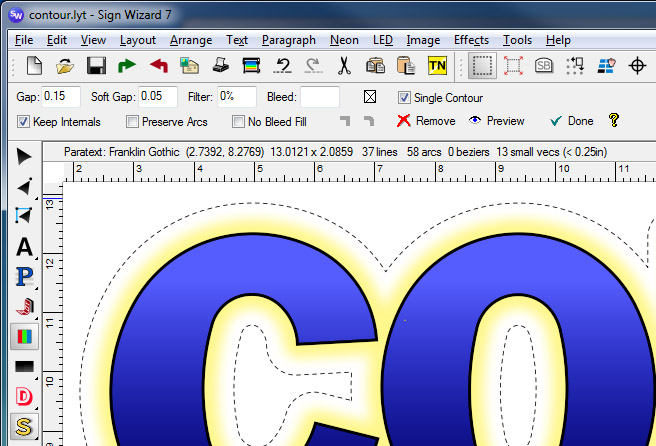
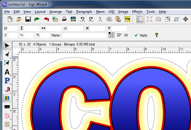
Here we have added a Dynamic Contour Cut path (Layout Menu - Dynamic Contours) to this text that has a black Outline and a yellow Glow. There is a field for the Gap amount, plus a "Soft Gap" for effects like Soft Shadow, Glow, and Feather. Now when the customer says he wants a red Outline to be added, no problem. The Contour Cut Path will automatically adjust, and there's nothing else that you have to do.
Using ParaText's Map to Path feature SW
Among the many new capabilities of Paragraph Text, Sign Wizard 7's next generation text engine, is a really flexible Map to Path feature. This goes far beyond mapping to an arc or a Warp-style Bezier curve. You can map to almost any path and you still retain the properties of text, meaning you can change the copy, change the font, adjust the kerning, etc. at any time.
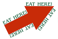 Map to Path will work with either an open loop or a closed loop. Start with a line of text, and then make a Group with the object that you want to map the text to. Go to the Paragraph Menu and select Map, then Map to Path.
The "EAT HERE!" example shows how you can adjust the kerning to position the text in the ideal position around the shape. Just use the usual kerning points, either letter by letter, or on the line of text as whole. As you increase or decrease the kerning, the text will map to the path around the shape. Of course you can also Scale the text to achieve similar design goals.
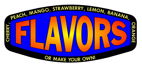 The "FLAVORS" example shows the text inside the shape.This is a simple adjustment of theSpace after Paragraph field in the Paragraph Text property bar. A positive value will move the text further from the path on the outside of the shape, while a negative value will move the text inside the shape.
Tips for Making Selections SW NW LW
With complex designs, it can be difficult to make selections just by clicking within the bounding box of an object since many objects may overlap. Here are some suggestions:
- Hold ALT as you make the selection.
- Use CTRL+TAB to cycle through the objects.
- Select the object in the Layers Tab.
- Click directly on a vector instead of inside the bounding box.
- Lock an object from editing by checking Locked in the Arrange Menu (also helps not to inadvertently move it when zoomed in).
- Consider other Grouping options, such as Group by Color.
If a design has become so complex that it is difficult to manage all of the objects, consider Grouping and moving some of them off the main layout area temporarily. Use Guidelines to establish the original position so that you can put the object back in place.
Using the Object Library LW
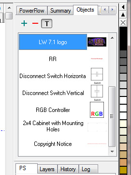 New to the free 7.1 upgrade, the Object Library is a really versatile feature that can be utilized in a number of ways. It is basically a library of content that can be added to your layouts very quickly without having to import or copy/paste from another application.
To add an object to the library, just select it and click on the green plus sign shown here at the top. You'll be prompted to give it a name. To insert an object back into your layout, just click and drag it or double click from the list.
You can add vector and/or bitmap objects, you can add Groups, you can add text objects, or any combination of these. One of the more innovative ideas we've seen is putting LED module product photographs here and dragging them into the appropriate spot on the title block as a way to identify and promote the module you're using.
Creating Sign Wizard Fonts and Font Editing SW NW
If you've been a customer for a while, then you remember the Font Editor Window, the innovative way to create and edit Sign Wizard fonts. The Font Editor Window was merged with the Layout Window many years ago, and the functionality remains to create your own high quality signmaking fonts.
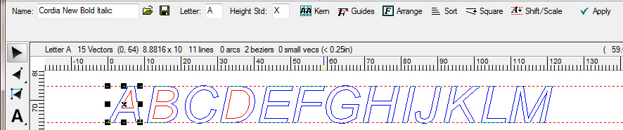
Here you can see an imported TrueType font and the Font Property Bar. Among the functions you can run on the font are creating a Kerning table, standardizing serifs with Guides, ensuring the letter height is consistent, and Squaring up vertical and horizontal angles. You can also, of course, vector edit the characters to ensure tangency (all Sign Wizard fonts are tangent within one degree).
If you're like me, there's nothing worse than a poor quality TrueType font that is being passed off as a "signmaking font." Signmaking fonts are properly kerned, smooth at large sizes, squared up (if applicable), and consistent heights across letters, with rounded characters going above and below the standard cap height.
If you need to use one of these poor fonts for a job, run it through these functions and in a few minutes, you can really improve its quality.
Copying a Populated Letter LW
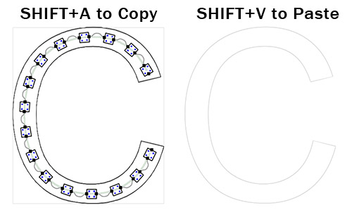 If you have a job with duplicate letters, you only have to populate the first letter in the set and then you can copy the modules to the duplicate letters. The procedure is easy:
First make sure that the letter being copied to is empty. If you did Pop All and it has modules, then select the modules in PowerFlow with SHIFT+A
and then press Delete. Now go back to the population that you want to copy from and select and copy the modules with SHIFT+A. Note that this both selects and copies the modules. Now click back into the empty duplicate letter to select it, and then use SHIFT+V to paste the modules in. Please remember, this is not CTRL+V, which is the standard Windows paste command.
This is different from copying modules within the same letter. To do this, make the selection of modules you want to copy, then hold CTRL and drag the modules to the new location.
How to handle bad artwork LW
The overall category of "bad artwork" is the most common reason that we hear from you for tech support for LED Wizard. It would be nice if there was a single "magic bullet" here that solves all these issues, but the diversity of the bad artwork requires us to have many tools to solve the problems.
So here is a quick summary of the data issue and the appropriate tool(s) to use:
| Issue | Tool | Comments |
| Excessive Data Points/Chords | Recreate with Bezier Curves | Best "global" clean up tool. |
| Isolated rough/jagged vectors | ALT-Smoothing | See documentation. |
| Exploded data (DXF) | Convert Exploded Vector Paths | Optional tolerance value. |
| Bad Loop Directions | Reorder Loops | Outside=Blue, Inside = Red. |
| Clean, spot-color bitmap art | Color Vectorize | See documentation. |
| Poor bitmap/photograph | On-Screen Digitize | Draw with lines, arcs, Beziers. |
| Poor bitmap/photograph | Match the font and type over | Use LW's easy text tools. |
| "Crowded/Busy" design file | Import Crop + Extraction Tool | See documentation. |
| Jagged, overlapping vectors / loop direction issues | Rasterize/Vectorize Filter | Rasterizes then vectorizes. |
| Design file in Corel/Illustrator | Windows Copy and Paste | Easy, no need to Export. |
| Any design file issue | Telephone/Email | Ask for cleaner data! |
Remember that we always prefer vector files over bitmap files. PDFs can be either vector, bitmap, or both. If you aren't sure if you have a vector file or bitmap file, turn off Show Colors. EPS, AI, and DXF are the other common vector formats. Many customers put statements directly on their web sites/order forms about the file formats that are supported.
How to solve the problem of missing objects when exporting LW
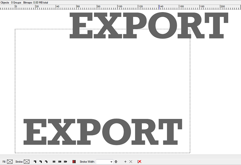 If you are having problems with missing objects when exporting, it is most likely due to one of two situations.
- The missing objects are outside of the layout area. Make sure that the dotted line of the layout area completely encloses all of your data. Layout Menu, Size to Fit is an easy way to ensure this.
- Some objects are grouped and some aren't. It is best to either Group All or have nothing selected when you export.
The Export Preview window will show what is being exported, so if you don't see everything that you're expecting, go back to the layout and look for one of the above situations.
How do I change the layout size? SW NW LW
The layout size can be resized numerically or graphically. The numerical method is the most precise if an exact size is required - just click on the Layout Menu then Layout Properties and enter the new height and width. The graphical method is faster than the numeric method, but not as exact. To make the layout size smaller, move the cursor to the upper right corner of the dashed black rectangle currently defining the layout size. When the cursor shape changes to a double-ended diagonal arrow, click and drag the mouse down and to the left until the desired size is shown. This method allows you to adjust the aspect ratio of the resulting layout area. To make the layout size larger, just click and drag that arrow up and to the right. It may take a couple tries to make the layout considerably larger.
Changing which power supplies are listed LW
 There are two options for determining which power supplies are listed:
1. Only list the power supplies for the brand that you have selected.
2. Also list "generic" power supplies, which are the MeanwellTM brand in the following watts: 40, 60, 80, 100, 120, 150, 185, 240, and 320.
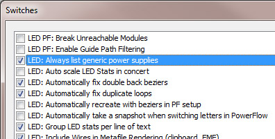
To change from one setting to the other, go to the Tools Menu and select Switches. Check or uncheck the third item down, "LED: Always list generic power supplies."
Please note that we do not display power supplies from a different LED brand once you have populated your letters or cabinets.
How do I use the Raceway Guideline feature? NW
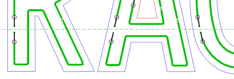 The Raceway Guideline will determine where the neon tubes are broken so that the housings can be placed in the raceway. Simply select Add Raceway Guideline from the Neon Menu, and a long-short dashed horizontal guideline will be inserted into the layout. Now just position this somewhere inside the raceway, and when you create the Auto Tube Layout or use the function Neonize, the tubes will be broken at the guideline.
How do I change the units of measure between imperial and metric? SW NW LW
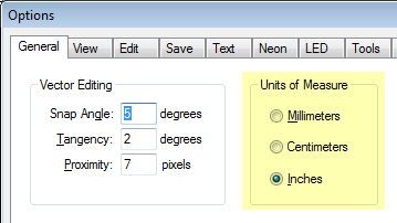 Go to the Tools Menu and select Options. The first tab is called General, and there will be a Units of Measure option that includes Millimeters, Centimeters, and Inches.
Setting up your Cutter/Plotter SW NW
By far the most common technical support issues we see have to do with setting up a cutter. There are a lot of variables here - the cutter brand, firmware version, cables, type of port, operating system, computer specs, cutter driver, Sign Wizard/Neon Wizard version, and more. It isn't practical to get into every scenario here, but there are some things that you can do to help diagnose the problem when the cutter isn't working right (or at all).
Is the cutter ready?
This covers the basics, including that it be plugged in (don't laugh, this has been the solution more times than you would think), media is loaded, a knife is installed, it is connected to the computer, and the Ready Light is on (or equivalent). Read the cutter's documentation to make sure you have it set up correctly.
Are the cutter and computer communicating?
The answer to this question confirms that we have a connection between the cutter and the computer, with a cable that works and the right port selected, or the Windows Printer Driver set up correctly (see below). Sometimes the cutter manufacturer provides a diagnostic tool that helps determine if there is a connection.
Is the software sending the data correctly?
If the answer to this is No, then it is most likely an issue with the actual cutter driver. Common problems here might be the size of the cut, poor corners, not starting or ending in the right place, loops not closing, or other problems. Most cutter drivers today are standardized across a certain brand's machines.
If you think the issue is with the driver itself, we are going to ask you for a screen shot of the driver details, which you can get by selecting Setup from the Device Menu in the Plot Manager. Take a screen shot of the driver with ALT+PrintScreen and paste it into an email.
To help with these and other issues, we have written a few How To documents that are posted on our Support area of the Aries Graphics web site. Of particular importance is the document titled: How to Configure WPD Ports in Sign Wizard and Neon Wizard.
If you have a current model cutter and a current operating system, then this is the way to connect your cutter!
Using the Fewest Modules Mode LW
Many newer LED modules are designed to be spaced at the maximum distance possible, and it is often the goal of a population to use the fewest modules to reduce cost. To help achieve these layouts, with the LED Wizard 7.1 update, we introduced the Fewest Modules Mode. This is simply an option that you select in the LED Menu prior to populating.
When used in conjunction with the Pop Round layout option, this will position the modules with the maximum physical spacing. Remember with this option that modules will not necessarily be positioned in corners, and there may be angled modules as well.
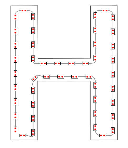
Another way to use the Fewest Modules Mode is with the PowerFlow editing tools. If you click and drag along the guide path to add modules, it will automatically space each module the maximum distance from the previous module. You'll notice that the wire drawings are straight in this mode, regardless of the LED spacing. One final point here is that you can still adjust the spacing with Increase Density (W) and Decrease Density (R).
How can I scale an object up or down and how do I maintain the aspect ratio as I scale? SW NW LW
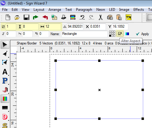 The default mode to scale an object up or down maintains the aspect ratio. This means that when you scale in one direction, the other direction scales to match so the object isn't distorted. You can scale an object either numerically or graphically.
This image shows the numeric option, highlighted in the upper left, where the "1" is the scale factor (entering "2" would double the size), "8" is the height, and "12" is the width. It also shows the graphical option, which is just to use the upper right or upper left control point and drag it up to scale up, or down to scale down. The Alter Aspect button lets you scale the height and width independently when it is selected.